
Circle Tool and Arc Tool
We previously used the Arc tool
to make convex/concave lines to
create profile for the ceiling molding.
tool
to make convex/concave lines to
create profile for the ceiling molding.  However, up till the the end of this Sketchup tutorial, we are not
going to use the Circle
However, up till the the end of this Sketchup tutorial, we are not
going to use the Circle tool.
Since this is a rather
fundamental tool, we are going to have a rather thorough
discussion regarding the Circle
tool at this section.
tool.
Since this is a rather
fundamental tool, we are going to have a rather thorough
discussion regarding the Circle
tool at this section.
There are also two other tools at the 'Drawing toolbar', namely Polygon tool
and Freehand
tool
and Freehand tool.
There is nothing
special about the Polygon tool since its usage is largely
similar with the Rectangle
tool.
There is nothing
special about the Polygon tool since its usage is largely
similar with the Rectangle tool.
Polygon tool
will create a regular Polygon entities, with 3 or more equal sides.
This tool provides us with option to enter the number of edges to
create and the radius of the polygon. Freehand tool is
somewhat similar with Line
tool.
Polygon tool
will create a regular Polygon entities, with 3 or more equal sides.
This tool provides us with option to enter the number of edges to
create and the radius of the polygon. Freehand tool is
somewhat similar with Line tool.
Freehand tool
is used to draw irregular hand-drawn lines which are comprised of
multiple line segments that are connected together. When the the
starting and ending points of the lines coincide, a face will be
created.
tool.
Freehand tool
is used to draw irregular hand-drawn lines which are comprised of
multiple line segments that are connected together. When the the
starting and ending points of the lines coincide, a face will be
created.
I have no plan to discuss the Polygon, and Freehand tools. Their usage are rather simple. Besides, I hardly use these tools. In the contrary, Arc and Circle tools are used quite frequently and some aspects should be known to optimally use the tools, so I will explain these two tools in a more detail fashion in this section.
Getting to know Circle and Arc Tool
SketchUp can only recognize straight lines and faces (flat surface). Hardly there is any object that consists of only one straight line. No wonder, in SketchUp, there is no function or command to thicken or to color one particular line.
Circles and Arches are basically just a number of straight lines of the same length stitched together to appear like a circle or an arc. Each line is called as a segment. The more number of segments created, the smoother the circle or the arc will appear. However, it will affect the file size and therefore heavier burden to the computer processor.
Circle Tool
Below is the Entity info window when the outline of a circle is selected (just the outline, not including the face)
 Right after the Circletool
is activated, we are given the opportunity to change the number of
its sides (segments) by typing in the desired number and then press
[Enter]. Initially, the number of segment provided by SketchUp is the
default circle's segments (24), or the last value that we set for the
this tool. The circle radius is determined after we choose its center
point using mouse click and move out the cursor or by typing in a
length value followed by [Enter].
Right after the Circletool
is activated, we are given the opportunity to change the number of
its sides (segments) by typing in the desired number and then press
[Enter]. Initially, the number of segment provided by SketchUp is the
default circle's segments (24), or the last value that we set for the
this tool. The circle radius is determined after we choose its center
point using mouse click and move out the cursor or by typing in a
length value followed by [Enter].
The strictest work flow of a circle creation is:
- Find a plane that will be used as the reference for the new circle orientation. You can use one the main axes, any existing face, or create a temporary face for the reference.
- Determine a point in the model that will be the center point, or
create a guide(s) using Tape Measure
 tool
and/or the Protractor
tool
and/or the Protractor tool
to obtain a precise location.
tool
to obtain a precise location. - Click the Circletool
and, if necessary,
change the number of segments to your liking.
- Move the cursor over the area to be used as the reference (as in point 'a'). If the circle plane is different than the referenced plane, press and hold [Shift] key to lock the orientation.
- Click at the point you want as the center point of the circle (point b) and,
- Move the cursor away to any direction, then click after the circle radius seems appropriate or type in any number using the keyboard then press [Enter] to set the radius precisely.
Step (f) can be made at any time using the entity info window as
shown previously. Step (c) can only be done if the circle has not been
converted into 3-dimensional shape. For the rest of the steps, editing
can be done using the Move/Copy tool.
Note that point (a) must be done correctly from the beginning, since
changing the orientation sometimes is not as simple as creating a new
circle from scratch.
tool.
Note that point (a) must be done correctly from the beginning, since
changing the orientation sometimes is not as simple as creating a new
circle from scratch.
Determining the plane where the circle will be created
Once we select the Circletool,
before clicking the mouse to determine the position of the circle's
center point , we must first determine on what plane the circle will
reside, or which plane will be used as a reference. If we use the
standard ISO view
and there is no other object that can be used as a reference, then the
circle can only be made on the plane perpendicular to the Blue Axis. Reference to any other axis can
only be done on the appropriate camera angle as shown in the animation.
view
and there is no other object that can be used as a reference, then the
circle can only be made on the plane perpendicular to the Blue Axis. Reference to any other axis can
only be done on the appropriate camera angle as shown in the animation.
| Tip & Trick |
| Determining reference
for the rotation plane
If the new circle will not be placed at any of the existing geometry (existing faces) we need to find a reference for the rotation plane of the circle. The same principle applies to the Polygon tool,
Rotate tool
and Protractortool.
Any of existing faces
and one of the main axes can be used as the reference. tool
and Protractortool.
Any of existing faces
and one of the main axes can be used as the reference. |
Normally, a circle is made on a face of an existing object. So just need to click at the face and the circle orientation will automatically follow the referenced face. Otherwise you need to select a particular face or one of the main axes as a reference and then lock the face orientation by pressing and holding the [Shift] key and then choose any position to be the center point of the circle.
Animation below shows, when the standard ISOview
is selected and no other object can be used as a reference, the
orientation of a new circle can only be set to the blue axis. We can
change the view as shown at the end of the animation, or create a
temporary object that can be used as references. As usual, after we
obtain an orientation reference, we press and hold [Shift] key until
after we click a certain point to set it as the center point of the new
circle.
 |
| Creating various circles with different orientation. |
What about Oval shapes?
SketchUp does not provide us with a special tool to create an oval or ellipse shape. To create an oval shape, we first create a circle, then reduce or enlarge one or both of the diameters to get the desired oval shape.
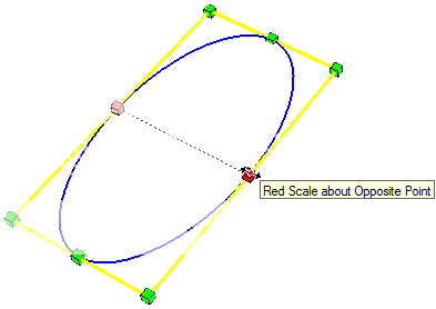 To resize a circle diameter, we
use Scale
To resize a circle diameter, we
use Scale tool
available on the Edit toolbar. Click once on the circle ,then select
the Scale tool so that a yellow bounding box with eight green grips is
displayed around the circle. Click one of the grips in the middle of
one of the bounding box edges (not one of the corner grips), and then
pull the grip out or in until the desired oval shape is achieved.
tool
available on the Edit toolbar. Click once on the circle ,then select
the Scale tool so that a yellow bounding box with eight green grips is
displayed around the circle. Click one of the grips in the middle of
one of the bounding box edges (not one of the corner grips), and then
pull the grip out or in until the desired oval shape is achieved.
| Tip & Trick |
| Scale Tool Scale tool is used to resize an existing object in the model by dragging one on the available sliding points. There are two modes of scaling using the measurement box: By specifying the sizing coefficient (default) or by determining the final dimensions of the altered aspect. For the second mode, we must add a value and its notation before pressing enter (such as 5' 3" for five feet and three inches). |
To obtain an accurate shape/size of the oval, it is better to type in the desired final value of diameter along with its unit notation (e.g. 150 cm) using the keyboard and then press [Enter]. Then the diameter we resize will have the final dimensions of 150 cm. Or, enter a value (e.g. 0.5) and press [Enter] then the new size of the diameter will be exactly half of the original.
Arc Tool
The illustration below shows an arc and a dimension information along with the Entity info of the arc. .
 Radius
information indicates the radius of the circle that forms the arc. As
we know, an arc is a segment of the circumference of a circle.
Radius
information indicates the radius of the circle that forms the arc. As
we know, an arc is a segment of the circumference of a circle.
In contrast to the circle tool, the information on the Entity Info window of an arc is different with the parameters available during its creation (as displayed in the measurement box). Bulge is not available in the entity info window and scaling will not always result as expected. This indicates that most of the time it is easier to create a new arc than editing an existing one using the entity info. Normally we first prepare two lines that will hold the starting and ending points of the arc, then determining the curve between the two lines.
The strictest work flow of an Arc creation is:
- Decide which line end(s) to start or to end the new arc.
- Activate the Arctool
and, if necessary, change the
number of segments of using the Measurement box.
- Click on the first point and click on the second point to set the beginning and the end of the curved line (both ends of the green line at the above picture), or enter its length using the keyboard and press [Enter]
- Move the mouse cursor towards any position between the two points and click or input the height of the protrusion (the red line at the above image), or type in the bulge value through the keyboard and press [Enter].
Step (b) can be done at any time using the Entity info window as shown above. As you can see the information on the Entity info window, one aspect that can be changed directly is the segments (point b). The other aspect that can also be changed is the radius of the arc (not included in the Measurement box). However, we usually are concerned more with how to make a seamless curve to a line/curve or a corner, not with the exact size of the arc itself.
Creating a perfect connection between an arc with a line or another arc.
Connection of an arc to a line or to another arch will look seamless if the two objects share a common characteristic.
 The Cyan
and magentaa line d
on the second
picture). The arc connection would be perfect if b (and c)
is the radius of each curve and b perpendicular to the line a.
For the second image, c is perpendicular to the line d.
The Cyan
and magentaa line d
on the second
picture). The arc connection would be perfect if b (and c)
is the radius of each curve and b perpendicular to the line a.
For the second image, c is perpendicular to the line d.
Colored curves in the picture are arcs with a certain radius. These
curvature form smooth curves that the arc is a continuation of the red
line (or that connects line  Similarly, between two curves /
arches. An arc (the black arc) can connect with another arc (the cyan
act) seamlessly when AC is a straight line, and AB and BC
is the radius of each corresponding curve. The illustration indicates
that the cyan arc
starts at the end point of the black arc AND the radius of the
cyan arc is in line with the radius of the black arc.
Similarly, between two curves /
arches. An arc (the black arc) can connect with another arc (the cyan
act) seamlessly when AC is a straight line, and AB and BC
is the radius of each corresponding curve. The illustration indicates
that the cyan arc
starts at the end point of the black arc AND the radius of the
cyan arc is in line with the radius of the black arc.
The connection point between the curve and another object is referred to as a tangent to the curve. You don't to need to even remember this, because SketchUp will provide color information when the connection is perfect with the inference "Tangent at Vertex." cyan inference indicates the arch merge perfectly to a line or to another curve, and magenta indicates that arch fits seamlessly with two lines and/or other arch.
To invoke the Magenta inference, the starting and ending points of the curve should form an isosceles triangle with the peak lies between these two points. When isosceles is achieved, the inference color will turn into magenta as seen in the animation below.
(Note: Line b, c and AC in the above illustrations are provided for explanation purpose only. If any of these lines does exist, no inference information will appear) |
| Creating curves with a smooth continuation from another curve or line(s) |
In another part of this General section, we will learn to create three-dimensional shapes based on circles and arches, e.i. to create balls, rings, tires and so forth.
Keep on Sketching ...Harrynov
 have not done any other mouse operation, we can continue
changing the last entered parameter through the keyboard. The size (or
slope) of
the object will automatically change every time [Enter] key is
pressed.
have not done any other mouse operation, we can continue
changing the last entered parameter through the keyboard. The size (or
slope) of
the object will automatically change every time [Enter] key is
pressed. 


 making changes or adding objects. The guide will be
positioned a certain distance from a known line/point in the model
(i.e. one of the Main Axis).
making changes or adding objects. The guide will be
positioned a certain distance from a known line/point in the model
(i.e. one of the Main Axis). 


