
SketchUp is not intended for engineering purposes that demand for high accuracy modeling. However, it is accurate enough to make 3D models larger than a few centimeters. For the purposes of architecture modeling, of course, SketchUp's level of accuracy is sufficient.
| Warning |
| Non Planar Face SketchUp automatically creates a face when a set of lines make a closed loop and are all in the same plane. However, Sketchup also makes a little approximation that even when some of the lines are a little off (not exactly in one plane), a face will still be created. This can be difficult when we try to do push & pull on the face. The results can be messy or not possible at all. Using inferences will avoid such problem. |
- Accuracy in measurements
- Accuracy of object positions
- Accuracy of object slopes.
Accuracy in measurements
Measurement Box
The surest way to make accurate dimensions and slopes is using Measurement Box. Almost every object has its own set of parameters depending on the current tools we choose (context sensitive). Here are some examples:| Tip & Trick |
| Measurement Box As indicated in "A Fresh Start", Measurement Box is one the three elements of SketchUp. Notice that there is no blinking cursor to make input or to edit value(s) in the input field. There no other way to enter parameter(s) other than typing blindly using the keyboard. |
- Line
 tool
: [Length]
tool
: [Length] - Rectangle
 tool
: [Wide, Length]
tool
: [Wide, Length] - Circle
 tool:
[Sides] [Radius]
tool:
[Sides] [Radius] - Polygon
 tool
: [Sides] [Radius]
tool
: [Sides] [Radius] - Arc
 tool;
[Sides] [Radius] [Bulge]
tool;
[Sides] [Radius] [Bulge] - Freehand
 tool:
None
tool:
None - Tape Measure
 tool
: [Length]
tool
: [Length]
- Protractor
 tool
: [Angle]
tool
: [Angle] - Scale
 tool
[multiplier], or with the unit symbol, [Desired dimension].
tool
[multiplier], or with the unit symbol, [Desired dimension].
[Bracket] indicates that you have
to press [Enter] after each entry.
Measurement Box is active only during an object
creation,
until we do another mouse operation. As long as we  have not done any other mouse operation, we can continue
changing the last entered parameter through the keyboard. The size (or
slope) of
the object will automatically change every time [Enter] key is
pressed.
have not done any other mouse operation, we can continue
changing the last entered parameter through the keyboard. The size (or
slope) of
the object will automatically change every time [Enter] key is
pressed. Scale Tool
| Tip & Trick |
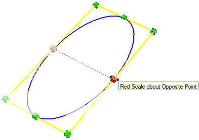
| Scale Tool Scale tool is used to change the size of existing objects in the model by dragging one on the available sliding points. Combining Scale tool with [Ctrl] key will scale object from its geometry's center point. Combination of Scale tool with [Shift] key will scale the object with some uniformity. |
tool
in Edit toolbar. When an object is selected using the Scale tool, there will be a bounding box with several scaling points that can be selected and dragged by the mouse. There are 24 scaling points for 3-dimensional objects, and 8 points for 2-dimensional objects. as seen in the figure below.
 To get an accurate scaling, Scale tool must also be
accompanied by entering parameters through the Measurement box. There
are two ways to use Measurement Box with the scaling tool. First, by
entering a value as the scaling factor, second by inserting a value
complete with dimensional unit(for example: 125cm) in order determine
to final dimension of the aspect being scaled.
To get an accurate scaling, Scale tool must also be
accompanied by entering parameters through the Measurement box. There
are two ways to use Measurement Box with the scaling tool. First, by
entering a value as the scaling factor, second by inserting a value
complete with dimensional unit(for example: 125cm) in order determine
to final dimension of the aspect being scaled.
Editing using Reference
I am not a fan of Scale tool because sometimes some aspects are not
completely controllable so that the result sometimes would not be as
expected. I prefer using one of the Edit tools and cutting and slicing
the object so that
elements of an object can be individually changed. Referencing is the next best thing in SketchUp after Push/Pull. By using references, we can make an object as accurate as possible (dimension, location, slopes) and use the object as a reference to make or to edit another object. This saves a lot of time.
Therefore, my work flow to create objects accurately is: Create initial object(s) and maintain its accuracy using Measurement box, and reference the object(s) during creating/editing of subsequent objects.
Reference to Another Object
The most effective and efficient way to edit an object is by referencing its change to an existing object. If the referenced object is accurate, then the edited object will also be accurate. |
| Push/Pull by referring to other object |
If we move the cursor to a face or any other point in another object to use it as reference, the face being edited will be at the the same plane with the referenced face/point. Again, this means that if the reference is accurate, then the change we are doing to the object will also be accurate. This is a time saver since we don't need type in any value whatsoever to make it accurate.
Redoing Last Operation to Another Object
Sketchup has the ability to apply one operation to separate objects
with identical result. This is done by double-clicking other object(s)
after an operation is completed with the initial object . The editing
operation can be
repeated as long as we do not select any other tool.  |
| Redo Operation with Double Clicking |
So if the first editing operation is measured accurately (i.e. using Measurement Box), all other operation will also be accurate
without having to make any entry with the Measurement Box.
The animation shows how we can repeat an OFFSET operation on several face shapes. For each double clicking, another shape with the same contour will be created exactly with the same distance from the original edges. If we specifically entered a certain length with the Measurement Box as the offset distance, then all the new shape will also have the same accurate offset distance. This is how I often do to make walls in SketchUp.
Adding Guides with a Certain Distance from a Known Position.
Another method to ensure accuracy is to add guides in the form of lines or dots to a model to be used as reference in making changes or adding objects. The guide will be
positioned a certain distance from a known line/point in the model
(i.e. one of the Main Axis).
making changes or adding objects. The guide will be
positioned a certain distance from a known line/point in the model
(i.e. one of the Main Axis). Guides is created using Tape Measure
tool or Protractortool.
Tape Measure tool is used to create a parallel guideline at
certain distance from another line, or to create a point at a certain
distance from another point. Protractor tool is used to
create a guideline with a specific angle to a line, (or two points)
that can be used as reference. Guides are usually removed immediately
after their use so as not to obstruct your view.  |
| Creating "Guides" |
Accuracy of Object Position
The easiest way to ensure accuracy of any object placement is to put
the object in reference to existing object (its midpoint, it's corner,
etc). If the referenced object has been positioned accurately than the
edited object will also accurate to that position. If there is no
object that can be used as a reference, of course, you can always make
Guides to place your object on the location of the guide.
Slope and Angle Accuracy.
We could always set every slope(s)/angle(s) of an object using
Protractortool as previously
discussed. Accurate but not too
practical. If you want to create a line that is parallel or
perpendicular to another line, it is much faster, yet still
accurate, to utilize SketchUp's Automatic Inference. | Tip & Trick |
| Automatic Inferencing
color By default, Black line indicates no inferencing is detected. Blue, Red, Green indicates that inference is made parallel to one of the main axes. Magenta and Cyan indicates parallelism, tangent or perpendicular with a certain existing line. Note that inferencing behavior is affected by your mouse clicking and hovering. Some can make a certain inference fail to appear. |
Parallel to one of the Main Axes
Most of the time, Main Axes are the main references when adding/editing an object. Therefore, it is advisable to always use them as the axes of your model (most of lines are in the model are aligned with one of these axes). Otherwise, main axes referencing may not as useful. |
| Parallel to one of the Main Axes |
tool,
Sketchup will automatically indicate whether the line is parallel with
one of the existing axis. Black indicates the line does not align with
any of the axes. The color will change to the color of the axes it is
parallel with. This is very useful, for example, when we want to
make a line perpendicular to the a floor, then we will move the cursor
upward until the resulting line turns blue
and click at desired position. Referencing to a line not parallel to any of the axes
In addition to the Main Axis inferencing, we can also obtain inferences from a curve or line that is not parallel to any of axis
Parallel to another line
 |
| Parallel another line |
Continuing a sloping line.
 |
| Continuance of a sloping line |
tool.
Move your mouse in the
direction that approximately extending the slope and click only when
the line turns Magenta.
Finding other inferences.
Perpendicular to to an edge.
 |
| Perpendicular Line |
Tangent and Perpendicular with an Equilateral Triangle
 |
| Creating a perfect curve |
The animation shows the following when we use the Arc tool. The first Magenta inference indicated that the starting and end point of the curve that will form an equilateral triangle from a point located between the two sides. Once we click that position, we will determine the curvature of the arc we are making. The curve color is Magenta to indicate that the radius of the circle that forms the curve is formed are tangent at the start and at end of the curve.
(...whew ... I need to brush up my trigonometry know....)
Harrynov
0 comments:
Post a Comment